Traduction en cours. Ce manuel est affiché en anglais en attendant sa version française.IP Router: IP Router manual, reference ZSYIPR
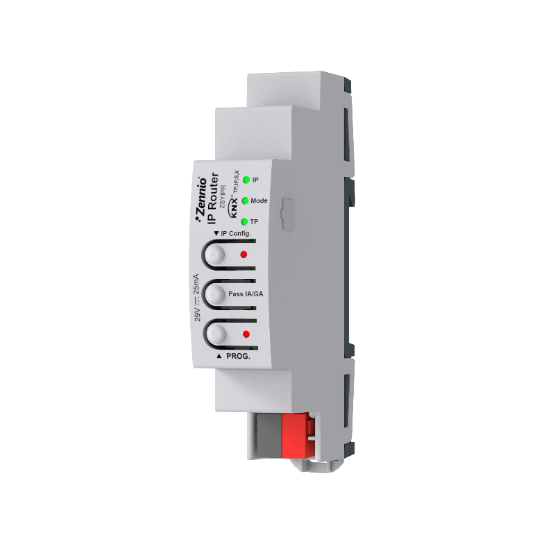
IP Router manual, reference ZSYIPR
KNX IP Router (IP – TP)
1.1. Features
IP Router is the Zennio solution for the interconnection of a KNX twisted pair (TP) line with a KNX IP network. The IP medium acts as the main line and the TP medium as the secondary line.
The main features of the IP Router are:
- Possibility of working as an area coupler.
- Possibility of working as a line coupler.
- Possibility of working as a segment coupler.
- Telegram filtering depending on the selected parameterisation options.
- IP interface with capacity for 10 simultaneous tunnelling connections, plus a direct connection for programming the device itself from ETS.
- Support for extended frames with a maximum APDU of 254 bytes.
- 5 LED indicators: one as programming mode indicator, two to indicate the status of the IP and TP media, another to indicate the operating mode of the coupler and another to indicate the IP address assignment method forced manually.
- “IP Conf.” button to temporarily change the IP address assignment method (static, DHCP or AutoIP) without using ETS.
- Manual control to allow the routing of all telegrams by group address or by individual address.
- KNX Security: support for KNX Data Security and KNX IP Security (see section 1.7).
- Security Proxy: functionality that translates secure multicast telegrams from one medium into plain telegrams sent to the other medium.
- Plug & Play: with the factory configuration, the device routes telegrams without prior programming (see section 1.2).
Note
The Security Proxy functionality is only available in ETS6. KNX Security must be enabled for it to work.
Note
The product information label includes a unique RESERVED KEY. It currently has no assigned use, but it is reserved for possible future use, so it is important to keep it.
1.2. Start-up and power loss
This device has no specific configuration to be executed during start-up. In its factory state, the IP Router has the following configuration, which allows the installation to be commissioned without programming it first:
- Individual address 15.15.0.
- Routing multicast address 224.0.23.12.
- IP address assignment via DHCP. If there is no DHCP server on the network, the device keeps routing telegrams via multicast.
- Routing of broadcast telegrams enabled.
- Tunnelling service available as soon as the device has a valid IP address.
Regarding power failures, two cases must be considered:
- Power failure on the TP line: the device is powered from the KNX bus of the TP line. If a power failure occurs on this line, the device is no longer powered, any kind of telegram routing is interrupted and it cannot be accessed for programming through ETS.
- Loss of connection to the IP network: the device stops routing telegrams between both media and indicates it through the IP LED (see section 1.3).
The parameterisation and configuration of the device are retained after a power failure.
1.3. LED indicators
The IP Router has 5 LED indicators that make it easier to monitor its status and detect problems.
- Programming LED: red LED that lights up if the device is in programming mode and blinks if it is in safe mode.
- IP LED: indicates the status of the IP medium (main line):
- Off: no Ethernet link and no IP address.
- Yellow (steady): Ethernet link and no IP address.
- Green (steady): Ethernet link and IP address.
- Green or yellow (blinking): sending or receiving KNX IP traffic (green if the device has a valid IP address; yellow otherwise).
- Red (steady): no Ethernet link and IP address.
- Red (blinking): no Ethernet link; an attempt to send a telegram over IP has failed.
- TP LED: indicates the status of the TP line (secondary line):
- Off: no power supply.
- Green (steady): powered.
- Green (blinking): receiving or sending telegrams.
- Red (blinking): a communication error has occurred: telegram sent without acknowledgement, sending without connection to the KNX bus or reception of a faulty telegram.
- Mode LED: indicates the operating mode of the coupler.
- Off: working as a line or area coupler.
- Green (steady): working as a segment coupler.
- Yellow (slow blinking, 500 ms period): “Pass GA” operation enabled.
- Yellow (fast blinking, 250 ms period): “Pass IA” operation enabled.
- Yellow (steady): “Pass GA” and “Pass IA” operation enabled.
- IP Conf. LED: indicates the IP address assignment method forced with the “IP Conf.” button (see section 1.4):
- Off: the method configured in ETS applies.
- Green (steady): DHCP assignment forced.
- Yellow (steady): AutoIP assignment forced.
Note
The yellow colour of the Mode LED indicates that the “Pass IA/GA” button has been pressed and the associated functionality is active: routing all telegrams (individual and/or group). It does not reflect the parameterisation made in ETS, i.e. if the coupler is parameterised to route all telegrams but the button is not pressed, the LED will light up green or remain off.
1.4. Buttons
The IP Router has 3 buttons that make it easier to control the device.
- Programming button: activates programming mode if the device is powered and, if the device is started with the button pressed, makes it enter safe mode (see section 1.5).
- “Pass IA/GA” button: provided that manual control has been enabled (see section 2.1), it allows all telegrams addressed to an individual address (Pass IA) and/or to a group address (Pass GA) to be routed to the other medium, regardless of the parameterised routing or filtering options. Starting with both modes inactive, successive presses go through the following sequence:
- First press: Pass IA active.
- Second press: Pass GA active.
- Third press: Pass IA and Pass GA active.
- Fourth press: Pass IA and Pass GA deactivated.
If 10 seconds or more have elapsed with any mode active, a new press deactivates them directly, regardless of the point of the sequence the device is at. This way, the integrator can easily deactivate the mode when it is no longer needed.
The activated mode remains until one of the following occurs:
- The device restarts.
- The mode is deactivated by pressing the button again.
- The maximum duration parameterised in ETS for manual control elapses.
Note
The “Pass IA/GA” button has no effect if manual control is disabled or if the device is in safe mode.
- “IP Conf.” button: allows the IP address assignment method of the device to be changed temporarily. Each long press of 3 seconds moves to the next method in the sequence:
- Static → DHCP → AutoIP → Static…
The “IP Conf.” LED indicates the forced method: green for DHCP, yellow for AutoIP and off when the method configured in ETS applies again (see section 1.3).
- If a static IP address has been configured in ETS, the sequence goes through the three methods.
- If DHCP has been configured in ETS, it is not possible to force a static IP address, as the device has no programmed IP address, subnet mask or default gateway. In this case, the sequence alternates between DHCP (LED off) and AutoIP (LED yellow).
Note
The change is temporary: after a restart, the device always applies the assignment method configured in ETS again.
1.5. Safe mode and factory reset
In safe mode, the device only keeps the functionality needed to reprogram or diagnose it:
- No telegram is routed from one medium to the other.
- Telegrams not addressed to the device itself are not acknowledged.
- It is still possible to establish a tunnelling connection.
Safe mode is indicated by one blink per second of the programming LED. It is entered in the following ways:
- Holding down the programming button while powering the device.
- Automatically, if the device restarts three times due to a malfunction with less than 10 seconds between restarts.
To exit safe mode, simply restart the device without holding down the programming button.
While in safe mode, a long press of 10 seconds on the programming button returns the device to its factory state, keeping its individual address. Outside safe mode it is not possible to reset the device manually, which prevents accidental resets.
Important
The factory reset erases the parameterisation and the KNX Security configuration of the device. It will be necessary to program it again from ETS.
1.6. IP Tunnelling
The IP Router includes an IP interface that allows up to 10 simultaneous tunnelling connections, for example, to program or monitor the installation from ETS over the IP network. Each tunnelling connection has its own individual address on the TP line.
In addition, the device supports a direct connection for its own programming from ETS, without the telegrams reaching the KNX bus.
The status of the tunnelling connections can be checked from ETS (see section 2.1.1).
1.7. KNX Security and Security Proxy
The IP Router is compatible with both types of KNX Security:
- KNX Data Security: protects the telegrams addressed to the device itself, for example, during its programming from ETS.
- KNX IP Security: protects communication on the IP medium, both tunnelling connections and multicast routing between IP routers.
The Security Proxy functionality translates secure multicast telegrams received from one medium into plain telegrams sent to the other medium, and vice versa. It also allows additional routing rules to be added for non-multicast telegrams.
For detailed information about the KNX Security functionality and configuration, please refer to the specific user manual “KNX Security”.